Mounting
The bearings should only be removed from their packaging immediately before mounting. Bearings with dry preservative should be protected against corrosion immediately after removal from the packaging.
ACHTUNG
The mounting area and the adjacent construction must be clean. Contamination impairs the accuracy and operating life of the guidance systems.
The bearings must not be tilted.
In the case of sealed bearings with a segment cutout, it must be ensured at all costs that the ends of the seal lips are not turned inside out (pay attention to the packing slip).
Mounting of bearings
Linear ball bearings KH
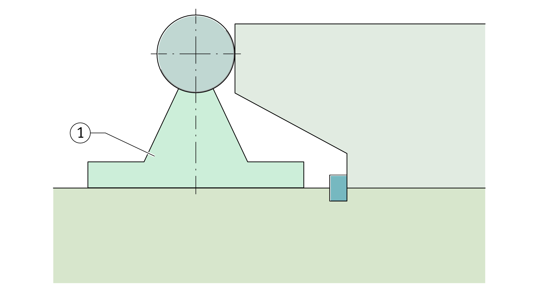
Linear ball bearings KH are pressed into the housing bore using a pressing mandrel, ➤ Figure. The mandrel dimensions must be in accordance with ➤ Figure.
The marked end face of the linear ball bearing should be in contact with the flange of the mandrel.
Linear ball bearings can be mounted more easily if the outside surface is greased.
Pressing in of linear ball bearings KH


Linear ball bearings KN..-B,KNO..-B, KB, KBS, KBO, KS, KSO and linear plain bearings PAB, PABO
Smaller bearings of these series can be slid into the housing bore by hand. For larger bearings, it is advisable to use a mounting mandrel, ➤ Figure.
The bearings are then located by means of retaining rings or a screw, ➤ Figure.
ACHTUNG
In the case of all bearings located by means of a screw, it must be ensured that the screw does not deform the bearing and the screw is secured against loosening.
Mounting of linear ball bearings
using fitting mandrel

Location of the bearing
using a screw

Alignment of bearings and shafts
Bearings arranged in series
Bearings arranged in series should be aligned with a continuous shaft, positioned against a stop and then screw mounted firmly in place.
Bearings arranged in parallel
Bearings arranged in parallel are aligned by measuring the spacing between the shafts (A1) or between the bearing outside diameters (A2), ➤ Figure. This spacing can also be defined by means of spacers.
The first shaft is set (datum shaft) and screw mounted. The second shaft is aligned by moving the table to achieve the required spacing.
Alignment of bearings arranged in parallel

the bearing outside diameters
Very long guidance systems
with supported shaft
In very long guidance systems with supported shaft, one shaft and support rail unit is first aligned by means of the shaft and screw mounted firmly in place in stages (datum shaft), ➤ Figure.
The procedure described in ➤ section is then carried out.
Alignment of a shaft and support rail unit by means of the shaft
Guidance systems with clearance-free or
preloaded bearings
Only one row of bearings arranged in series should be set clearance‑free or preloaded. The bearings parallel thereto should have a substantial operating clearance.
Parallel shaft and support rail units
Clamp the datum support rail against a stop, ➤ Figure.
Clamping of the support rail when using two shaft and support rail units TSUW


Setting the operating clearance
Setting bearings clearance-free
In the case of linear ball bearings KBS and slotted housings, the operating clearance can be adjusted. The screw must be adjusted until resistance to further rotation can be felt between the shaft and bearing.
ACHTUNG
The adjusted bearing should not be rotated any further on the shaft.
Setting the preload
Preloaded bearings are set clearance-free on a master shaft that is smaller than the actual shaft in the application by the amount of the preload dimension.
Suspended arrangement
of guidance system
Suspended shaft guidance system
with drop guard
